STB 14 – Circuit and Electronic Laboratory
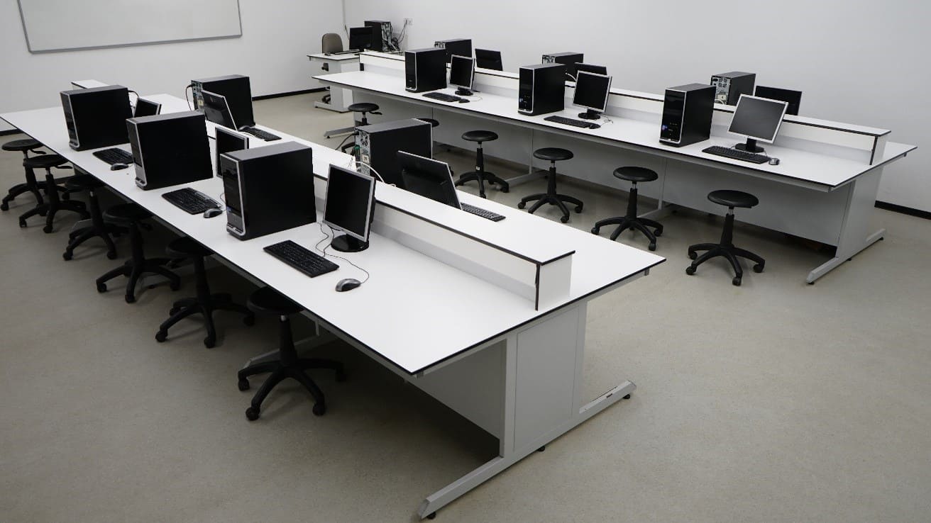
Electronics Laboratory is the fundamental practical learning area for Electrical Engineering students and other engineering disciplines. The laboratory is the laboratory where the student performs basic electronic experiments in the scope of EELE202 (Circuit Theory I) and EELE301(Circuit Theory II). The Laboratory consists of Voltage, current, resistance, and power measuring instruments. AC/DC power and signal generators, and AC/DC oscilloscopes are present in the Laboratory. Experiments on RLC circuits can be reliably done. Transformers, impedance measurement. Practical usage of basic instruments for measurements and analysis of electronic circuits can be performed. Experiments on rectifier diodes, Zener diodes, and transistors (BJT and FET) are done in advanced undergraduate electronic courses.
The experiments conducted in this laboratory are as follows:
- Kirchhoff’s Law
- Resistor Networks
- Thevenin’s Method
- Superposition Theor
- Capacitor Charging and Discharging Process
- AC Analysis using PSPICE
- AC Sweep Analysis using PSPICE
- AC Bridge Circuits
- Wien-Bridge Oscillator using OPAMP
- Thevenin Theorem and Maximum Power Transfer for AC Circuits
- Three-Phase Circuits
- The Semiconductor Diode
- Half-Wave & Full-Wave Rectification
- The Zener Diode
- DC Behavior of Bipolar Junction Transistor (BJT)
- AC Behavior of the BJT Common-Emitter Amplifier
- Analyzing Frequency Response of 1st Order Passive Filters
- Low-Frequency Response of the BJT Common-Emitter Amplifier
- High-Frequency Response of the BJT Common-Emitter Amplifier
- Operational Amplifiers
- Common-Emitter Amplifier with Parallel-Voltage Feedback